Transformer Tank Manufacturing Process: A Complete Step-by-Step Guide
From engineering design and steel preparation to welding, testing, coating and shipment — a technical guide for transformer OEMs, EPC contractors, utilities and procurement teams.
Overview
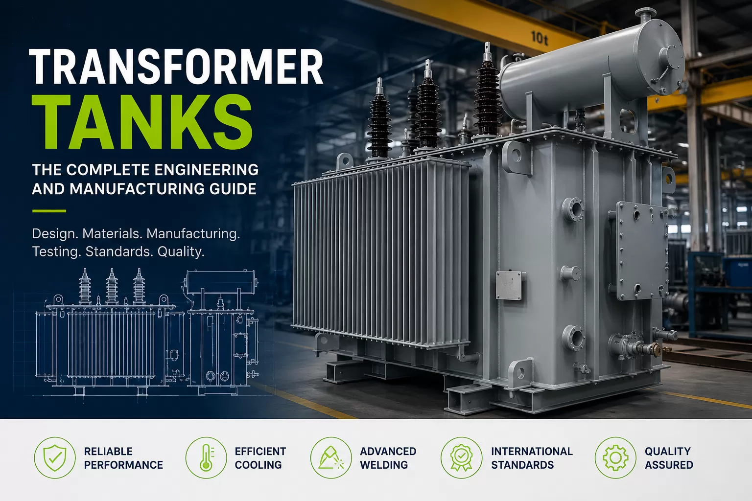
Transformer tank manufacturing is a precision-controlled fabrication process. The tank must protect the transformer active part, safely contain insulating oil, support thermal management and remain structurally reliable throughout transportation, installation and long-term service.
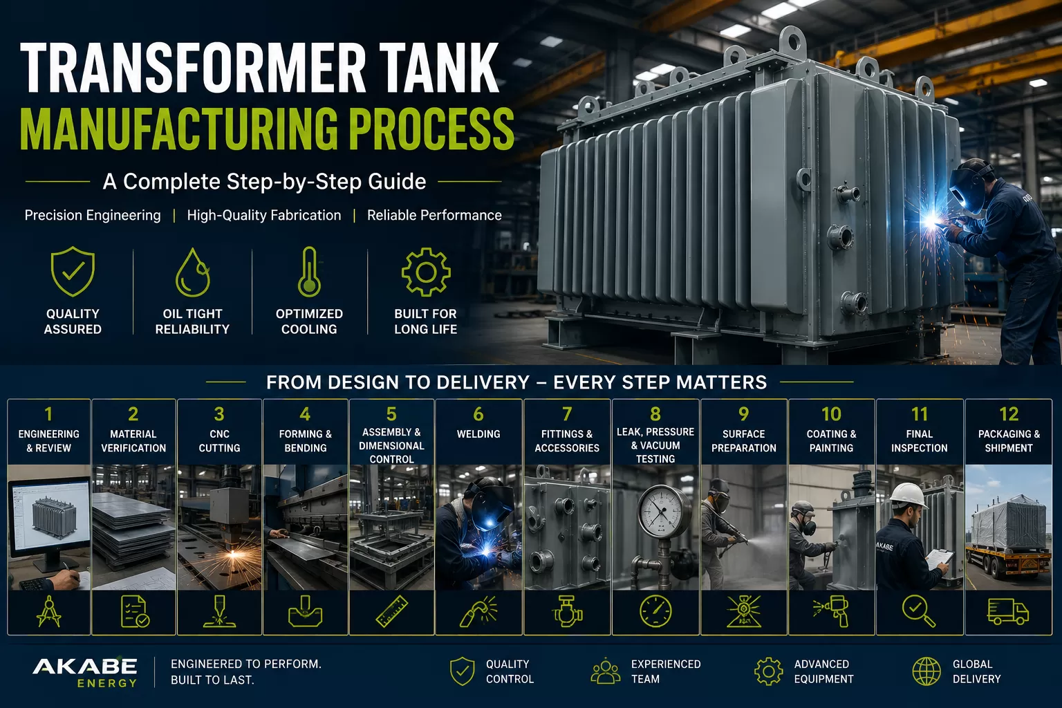
Small dimensional or welding errors can affect oil tightness, component alignment and overall transformer reliability. This guide explains the manufacturing workflow from the first engineering review through material verification, CNC cutting, forming, assembly, welding, leak and pressure testing, surface preparation, coating, final inspection, packaging and shipment.
1. Engineering Design and Requirement Review
Production begins before any steel is cut. The transformer manufacturer's drawings and project requirements are converted into fabrication-ready tank documentation.
Engineers review transformer rating, oil volume, active-part dimensions, internal clearances, cooling requirements, pressure and vacuum conditions, transportation constraints, lifting arrangements and installation requirements.
The tank geometry, cover, base frame, bushing positions, radiator or corrugated-panel interfaces, valves, lifting lugs, jacking points and customer-specific fittings are defined in detailed drawings.
Structural verification should consider wall thickness, stiffener arrangement, oil load, lifting forces, transport loads and the pressure or vacuum conditions expected during manufacturing and service.
2. Steel Selection and Material Verification
Transformer tanks are commonly fabricated from structural carbon steel, while corrugated panels may use thinner cold-rolled steel selected for forming performance. Material selection depends on structural requirements, tank geometry, welding procedures and the specified service environment.
Before production, plate and profile materials should be checked against the project specification and relevant material certificates. Traceability helps ensure that the steel released to production corresponds to the approved grade and thickness.
For specialized environments, corrosion-protected steel or stainless steel components may be specified.
3. CNC Cutting
Steel plates and structural components are cut according to approved production drawings. CNC laser or plasma systems can improve repeatability, dimensional accuracy and material utilization.
Accurate cutting is important because errors introduced at this stage can accumulate during assembly and create alignment, welding or dimensional problems later in production.
Cut parts are identified and prepared for the next forming and assembly operations.
4. Forming and Bending
Tank walls, base components, covers, brackets, reinforcement pieces and other fabricated parts are formed using suitable bending equipment such as CNC press brakes.
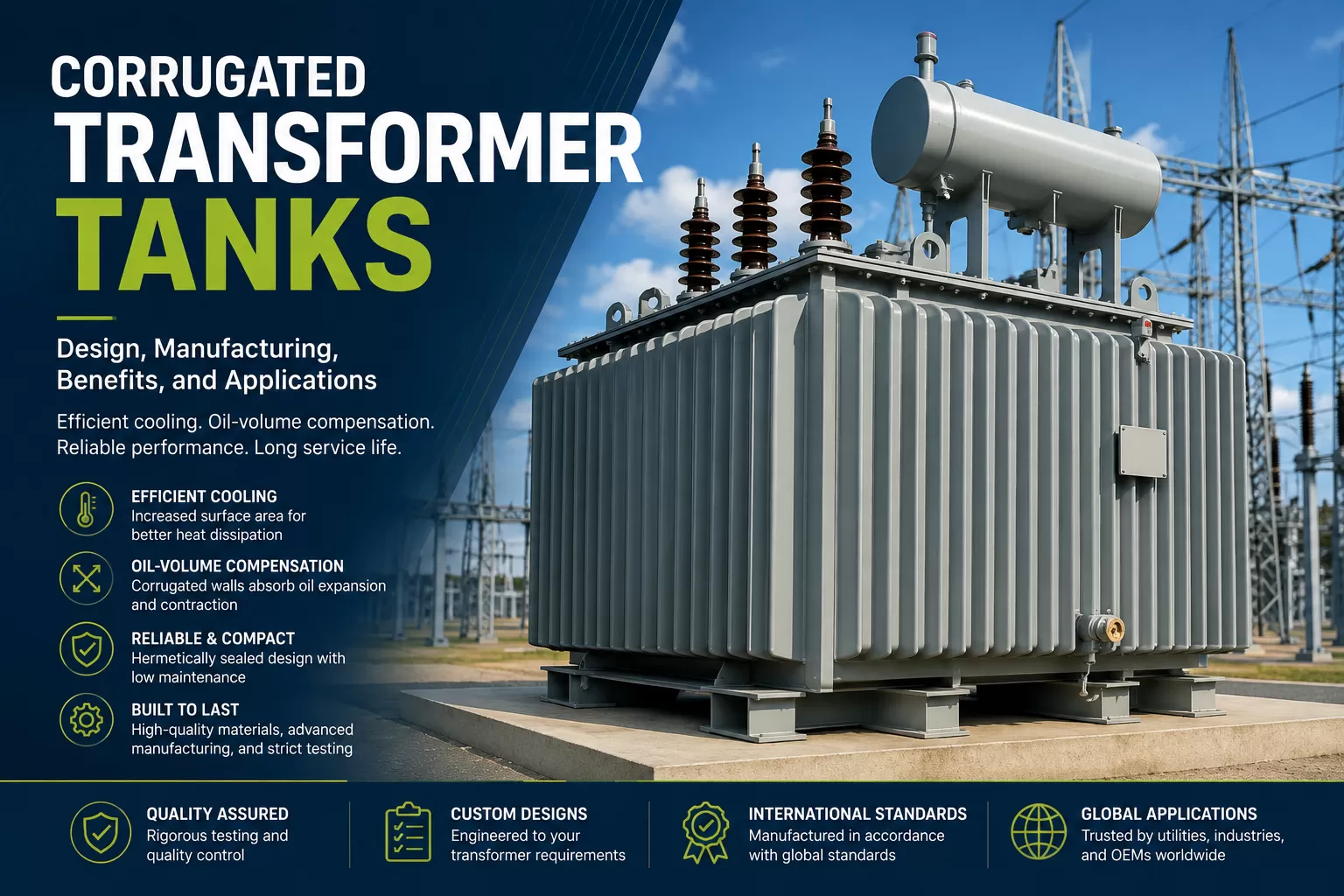
Where corrugated transformer tanks are manufactured, specialized forming equipment creates the corrugated panels. Corrugation depth, pitch, height and profile consistency influence both mechanical behavior and cooling performance.
Forming accuracy is therefore not only a manufacturing issue; it also affects the tank's final structural and thermal performance.
5. Assembly and Dimensional Control
Cut and formed components are positioned in fixtures or structural jigs before final welding. Controlled assembly helps maintain the overall tank geometry and the location of critical interfaces.
Important dimensions include cover alignment, mounting points, bushing or turret positions, radiator connections, base dimensions, fittings and accessory locations.
In-process dimensional checks reduce the risk of discovering accumulated tolerance errors after welding is complete.
6. Transformer Tank Welding
Welding is one of the most critical stages because weld quality directly affects structural strength and long-term oil tightness.
Qualified welding procedures are used to join tank walls, base frames, reinforcement components, corrugated panels and pressure-boundary connections. Depending on the component and production setup, processes can include GMAW/MIG, SAW, TIG or FCAW.
Welding sequence should be controlled to limit distortion, particularly on large flat steel sections. Excessive distortion can later cause problems with covers, flanges, radiator connections and gasket sealing surfaces.
Critical welds are visually inspected and, where required by the project, additional non-destructive testing can be applied.
7. Fittings and Accessories
After or during structural assembly, the required fittings and accessories are installed according to the approved drawing.
Typical items can include lifting lugs, jacking pads, earthing terminals, drain connections, filter valves, thermowells, pressure-relief connections, mounting flanges and other customer-specific interfaces.
Their position and dimensions must be controlled because the completed tank must integrate correctly with the transformer active part and auxiliary equipment.
8. Leak, Pressure and Vacuum Testing
Testing verifies that the fabricated tank can contain insulating oil and withstand the mechanical conditions specified for the project.
Leak testing focuses on welded seams, flanges, fittings and other potential leakage points. Depending on the quality plan, methods may include pressure testing with air or gas, soap-solution checks, tracer methods or other project-specific procedures.
Positive-pressure testing can be used to verify seam integrity and confirm that no unacceptable leakage or permanent deformation occurs.
Where required, vacuum testing verifies that the tank can tolerate negative pressure associated with processes such as oil filling or degassing without permanent deformation.
Selected welds may also be evaluated using non-destructive testing methods such as radiographic or ultrasonic inspection when specified.
9. Surface Preparation
A durable coating system depends on correct surface preparation. Rust, mill scale, weld spatter, oil and other contaminants must be removed before painting.
Shot blasting or abrasive blasting is commonly used to create a clean surface and suitable profile for coating adhesion. Project specifications may define the required preparation standard.
Surface cleanliness should be protected between blasting and coating to reduce the risk of contamination or flash rust.
10. Protective Coating and Painting
Transformer tanks are often exposed to outdoor, industrial, humid or corrosive environments for long periods. The coating system therefore forms an important part of long-term corrosion protection.
A project may specify primer, intermediate and topcoat layers according to the required corrosion category, dry-film thickness, color and service environment.
Coating inspection can include visual checks and dry-film-thickness measurements at defined locations.
11. Final Quality Inspection
Final inspection confirms that the completed transformer tank conforms to the approved drawings and project quality requirements before release.
Typical inspection points include overall dimensions, mounting and interface locations, weld condition, leak integrity, surface finish, coating thickness, corrugation consistency where applicable, and the position of fittings and accessories.
Inspection and test records, material certificates, welding documentation and coating records may be compiled into the project documentation package to support traceability.
12. Packaging and Shipment
After acceptance, the tank is prepared for transportation. Openings and sensitive interfaces should be protected against contamination and transport damage.
The packaging and transport arrangement depends on tank dimensions, lifting points, route limitations and customer requirements. Large tanks may require dedicated transport planning and verified tie-down or lifting arrangements.
A controlled shipment process helps preserve the dimensional and surface quality achieved during manufacturing.
Manufacturing Quality: Why the Process Matters
A transformer tank is not simply a fabricated steel enclosure. Its dimensional accuracy, weld integrity, oil tightness, structural strength and corrosion protection directly influence how reliably the complete transformer can be assembled, transported and operated.
For this reason, quality control should be integrated throughout production rather than treated only as a final inspection activity.
For transformer OEMs and EPC contractors, supplier evaluation should therefore consider engineering capability, material control, welding discipline, inspection documentation, testing capability and the ability to manufacture custom tanks according to approved drawings and project-specific requirements.
Transformer Tank Manufacturing Process – Summary
- Engineering design and requirement review
- Steel selection and material verification
- CNC cutting
- Forming and bending
- Assembly and dimensional control
- Welding
- Installation of fittings and accessories
- Leak, pressure and vacuum testing as required
- Surface preparation
- Protective coating and painting
- Final quality inspection and documentation
- Packaging and shipment
Frequently Asked Questions
What is the transformer tank manufacturing process?
It is the controlled sequence of engineering, material preparation, cutting, forming, assembly, welding, testing, surface treatment, coating, inspection and shipment used to produce a tank that meets transformer and project requirements.
Why is welding important in transformer tank manufacturing?
Welds form the structural and oil-containing boundaries of the tank. Welding quality therefore affects mechanical integrity, dimensional stability and leakage risk.
How are transformer tanks tested for leaks?
Leak verification can include positive-pressure methods, soap-solution checks, tracer methods or other project-specific procedures, with particular attention to welded seams, fittings and flanges.
Why are transformer tanks vacuum tested?
Where the transformer manufacturing or oil-filling process requires vacuum conditions, the tank must be able to withstand external pressure without unacceptable permanent deformation.
How are transformer tanks protected against corrosion?
The steel surface is prepared by methods such as abrasive or shot blasting and then coated with a paint system selected for the specified service environment and corrosion category.
Can transformer tanks be custom manufactured?
Yes. Dimensions, interfaces, cooling arrangements, fittings, lifting points, base structures and coating systems can be engineered according to transformer and customer requirements.
About Akabe Energy
Akabe Energy manufactures transformer tanks for power and distribution transformer applications. Projects can be developed according to approved drawings, technical specifications, operating conditions and customer-specific requirements, with controlled fabrication, welding, testing, surface preparation and final inspection processes.