Transformer Tanks: The Complete Engineering and Manufacturing Guide
A technical reference for power engineers, utility procurement teams, EPC contractors, and switchgear specifiers.
1. What is a Transformer Tank?
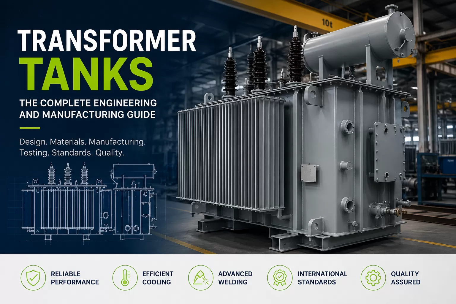
A transformer tank is the structural steel enclosure that houses the active part of a power or distribution transformer — the core, windings, tap changer, and insulating oil. It is not simply a metal box. A transformer tank is a precision-engineered pressure and containment vessel designed to withstand internal oil pressure, vacuum during oil filling, thermal expansion, short-circuit forces, seismic loading, and decades of outdoor exposure without leaking a single drop of insulating fluid.
Every transformer tank must simultaneously perform several jobs: mechanical protection of the active part, electrical insulation support, thermal management through its cooling surface, environmental sealing against moisture and dust ingress, and, in many designs, structural mounting for radiators, conservators, bushings, tap changers, and control cabinets. Because the tank is the interface between the internal high-voltage components and the external world, its design directly affects transformer reliability, service life, and safety.
In the global power transmission and distribution supply chain, transformer tanks are manufactured by specialized fabricators such as Akabe Enerji, who supply utilities, transformer OEMs, and EPC contractors with tanks built to exact engineering drawings and international quality standards.
2. Why Transformer Tanks Matter
The transformer tank is often overlooked in discussions about transformer performance, which tend to focus on the core and windings. In practice, tank design and fabrication quality determine whether a transformer survives its rated 30–40 year service life or fails prematurely.
A poorly welded seam, an undersized stiffener, or an incorrectly specified steel grade can lead to oil leaks, moisture ingress, reduced dielectric strength, and ultimately transformer failure — an event that, for a large power transformer, can cost a utility millions of dollars in replacement, lost generation capacity, and grid instability. Tank failures are also a leading cause of unplanned outages in aging transmission networks.
Beyond containment, the tank surface itself is frequently part of the cooling system. In ONAN (Oil Natural Air Natural) designs, the corrugated fin surface of the tank is the primary heat-rejection path. This means tank geometry is a thermal engineering decision, not just a structural one — undersized cooling surface area leads to elevated hot-spot temperatures and accelerated insulation aging.
3. Main Components of a Transformer Tank
A complete transformer tank assembly is made up of several interdependent structural and functional elements, each engineered to a specific mechanical and electrical function.
- Main Tank Body: The primary welded steel shell that contains the core, windings, and insulating oil.
- Tank Cover (Top Plate): A removable or welded lid providing access for assembly, bushing mounting, and internal inspection.
- Base Frame / Skid: Structural steel base supporting the tank weight, oil weight, and allowing for crane lifting, rail transport, or roller skidding.
- Radiators or Corrugated Fins: Cooling surfaces that reject heat generated by core and winding losses.
- Conservator Tank: An expansion vessel mounted above the main tank that accommodates oil volume changes due to temperature.
- Bushing Turrets: Reinforced openings for high-voltage and low-voltage bushings to pass through the tank wall or cover.
- Tap Changer Compartment: A dedicated chamber, sometimes with its own oil compartment, housing the on-load or off-circuit tap changer mechanism.
- Lifting Lugs and Jacking Pads: Structural attachments engineered to carry the full transformer weight during lifting and installation.
- Pressure Relief Device Mounting: A reinforced port for the pressure relief valve that protects the tank from internal overpressure events.
- Ground Pads: Welded lugs providing a verified earthing connection point.
- Inspection Manholes: Bolted access covers allowing internal inspection without full oil drainage in some designs.
- Valves and Drain Points: Oil sampling valves, drain valves, and filter press connections.
4. Types of Transformer Tanks
Transformer tank design varies significantly based on transformer rating, application, and oil expansion management philosophy. Below are the primary tank types used across distribution and power transformer classes.
4.1 Hermetically Sealed Tanks
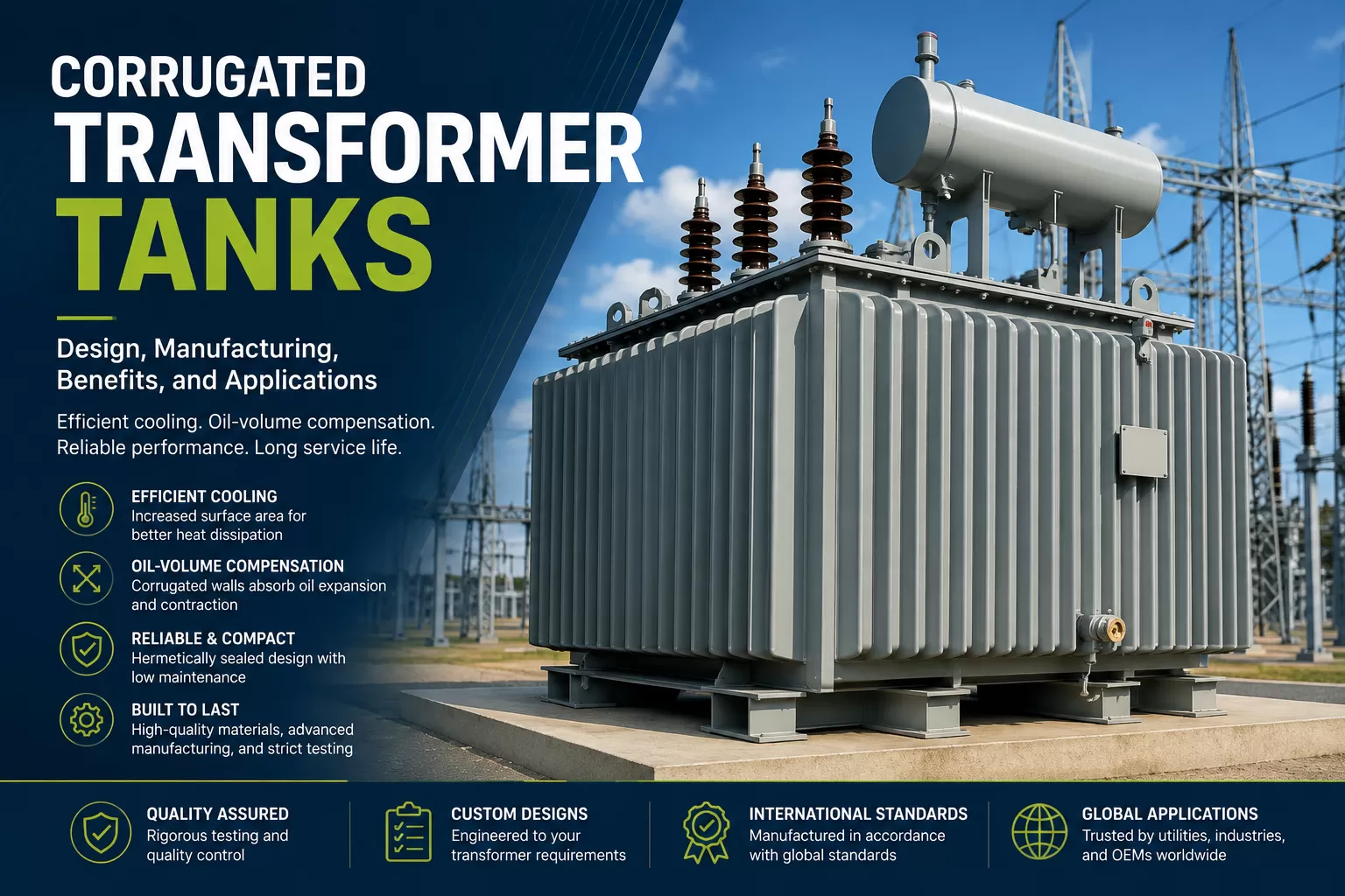
Hermetic tanks are fully sealed, gas-cushioned enclosures with no direct contact between the oil surface and outside air. Oil expansion is absorbed either by corrugated fin flexing or by a nitrogen gas cushion, eliminating the need for a conservator. This design is common in distribution transformers up to roughly 2500 kVA because it minimizes oil oxidation and moisture absorption, extending oil life significantly.
4.2 Conservator Tanks
Conservator-type tanks use a separate, smaller expansion tank mounted above the main tank, connected via a pipe. As oil temperature rises and falls, the oil level in the conservator moves up and down instead of stressing the main tank wall. A breather with silica gel or a membrane bag typically protects the conservator's air space from moisture. This design is standard for medium and large power transformers.
4.3 Corrugated Wall Tanks
Corrugated tanks use pressed steel fin panels welded directly onto the tank wall. The corrugations flex slightly to absorb oil expansion while also serving as the primary cooling surface. This design is popular for small and medium distribution transformers because it eliminates separate radiators, reducing both manufacturing cost and the number of potential leak points.
4.4 Radiator-Type Tanks
For larger power transformers where corrugated panels cannot provide sufficient cooling surface area, detachable or fixed radiator banks are bolted or welded to the tank wall. Radiators can be equipped with cooling fans (ONAF) or oil pumps (OFAF/OFWF) to increase heat dissipation for high-capacity units.
4.5 Custom Engineered Tanks
For special applications — mobile substations, offshore platforms, rail traction transformers, or GIS-integrated substations — tanks are custom designed around unique space, transport, and seismic constraints. Custom tanks may include reinforced skids for horizontal transport, explosion-proof pressure relief systems, or special stainless steel construction for corrosive coastal environments.
Transformer Tank Types Comparison
| Tank Type | Typical Rating Range | Oil Expansion Method | Maintenance Level | Typical Application |
|---|---|---|---|---|
| Hermetic | Up to 2500 kVA | Corrugated fin flex / gas cushion | Very low | Distribution networks |
| Conservator | 5 MVA – 500+ MVA | Separate expansion vessel | Moderate | Power transformers, substations |
| Corrugated | Up to 5000 kVA | Fin flexing | Low | Urban and rural distribution |
| Radiator | 10 MVA and above | Conservator + radiator cooling | Moderate to high | Grid and generator step-up transformers |
| Custom | Application-specific | Varies by design | Varies | Mobile, offshore, rail, special projects |
5. Transformer Tank Materials
Material selection for a transformer tank balances mechanical strength, weldability, corrosion resistance, and cost. The overwhelming majority of transformer tanks are fabricated from hot-rolled low-carbon steel plate, selected for its predictable weld behavior and structural performance under pressure and thermal cycling.
- Structural Steel Plate: Typically grades such as ASTM A36, S235JR, or S355JR (EN 10025), chosen based on required yield strength and plate thickness.
- Stainless Steel: Used selectively for bushing turrets, fasteners, or entire tanks in offshore and highly corrosive coastal environments.
- Corrugated Fin Steel: Thin-gauge cold-rolled steel pressed into fin profiles, requiring precise formability and weld compatibility with the main tank plate.
- Gaskets and Seals: Nitrile rubber (NBR) or cork-nitrile composites rated for long-term oil immersion without swelling or hardening.
- Fasteners: Zinc-plated or hot-dip galvanized high-strength bolts for external structural connections.
Steel Grades Reference Table
| Standard | Grade | Yield Strength (MPa) | Typical Use |
|---|---|---|---|
| ASTM A36 | A36 | 250 | General structural plate |
| EN 10025-2 | S235JR | 235 | Standard tank wall plate |
| EN 10025-2 | S355JR | 355 | High-stress tank walls, base frames |
| ASTM A283 | Grade C | 205 | Light structural components |
| EN 10130 | DC01 | Varies | Corrugated fin cold-rolled sheet |
6. Engineering Design Process
Transformer tank design begins long before any steel is cut. The engineering team translates the transformer OEM's or utility's electrical and mechanical requirements into a fully dimensioned, stress-verified structural design.
- Requirement Review: Voltage class, MVA rating, oil volume, core and coil dimensions, transport constraints, and site altitude/seismic zone are reviewed.
- 3D Modeling: The tank geometry, bushing turret positions, radiator mounting points, and internal clearances are modeled in CAD, referencing the transformer OEM's general arrangement drawing.
- Structural Calculation: Wall thickness, stiffener spacing, and cover plate design are calculated against internal pressure, vacuum rating (often full vacuum for oil filling), and short-circuit withstand forces.
- Thermal Verification: Cooling surface area is checked against the transformer's total loss profile to confirm the design meets top-oil and hot-spot temperature rise limits.
- Shop Drawing Release: Fabrication-ready drawings, including weld symbols, NDT requirements, and bill of materials, are issued to production.
- Design Review and Sign-Off: Drawings are reviewed against the applicable standard (commonly IEC 60076-1) before manufacturing release.
7. Manufacturing Process
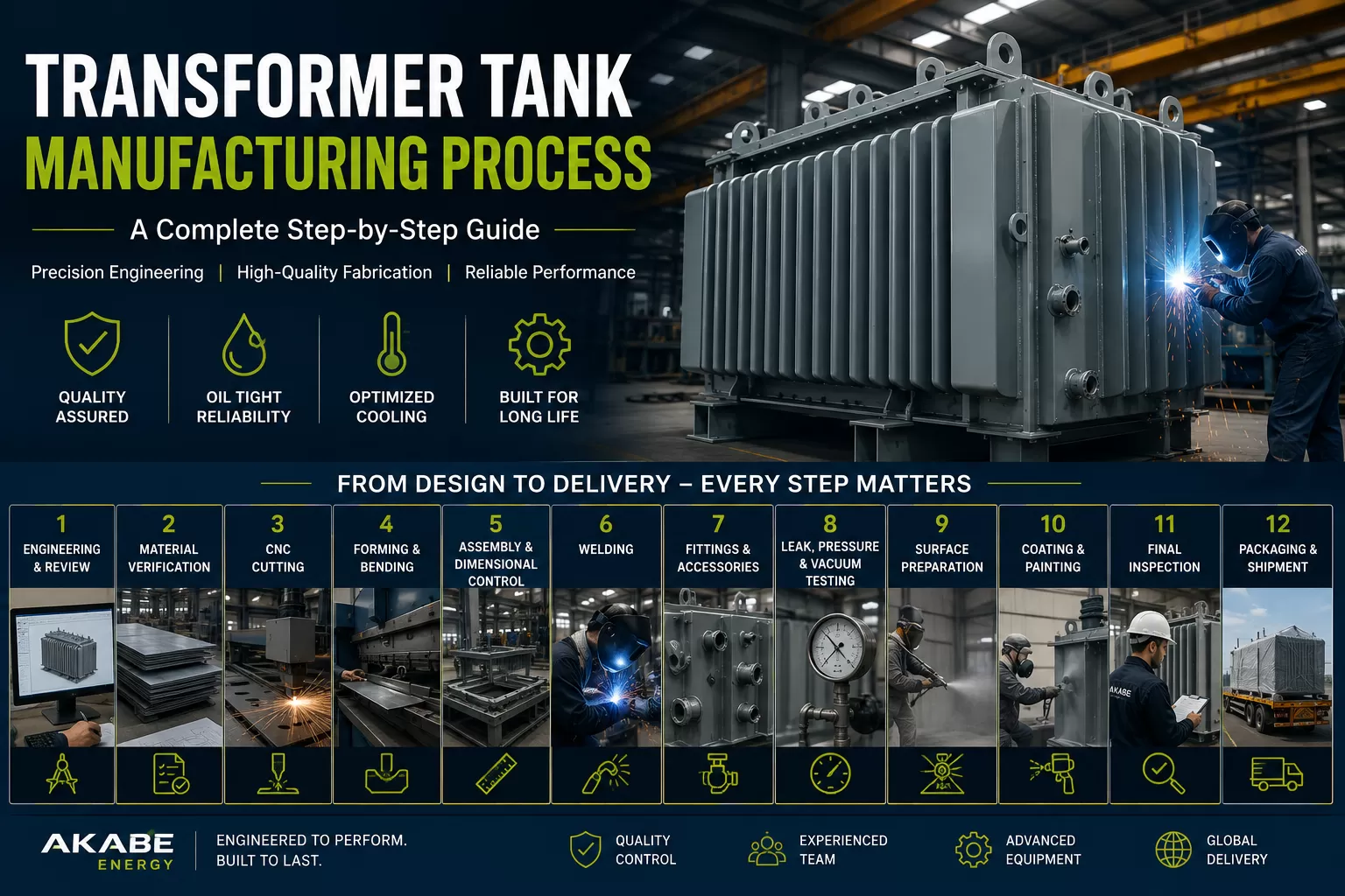
Transformer tank manufacturing is a multi-stage industrial process requiring tight dimensional control at every step, since even small deviations compound across a large welded structure.
7.1 Design
Fabrication-ready drawings are issued from the engineering department, including cutting lists, weld maps, and inspection checkpoints.
7.2 Steel Selection
Plate and profile steel are selected against mill certificates, verifying chemical composition and mechanical properties match the specified grade before release to cutting.
7.3 CNC Cutting
Steel plates are cut using CNC plasma or laser cutting systems, guided directly from CAD nesting files to achieve dimensional accuracy and minimize material waste.
7.4 Bending
Press brakes form tank wall sections, stiffeners, and corrugated fin profiles to the exact bend radii specified in the design.
7.5 Assembly
Cut and formed components are tack-welded into position using structural jigs to hold dimensional tolerances before full welding begins.
7.6 Welding
Qualified welders complete structural and pressure-boundary welds following approved welding procedure specifications (WPS).
7.7 Leak Testing
The assembled tank undergoes pressure and vacuum testing to confirm every seam is fully oil- and gas-tight before proceeding to surface preparation.
7.8 Sand Blasting
Abrasive blasting removes mill scale, rust, and weld spatter, achieving the surface profile required for coating adhesion, typically to Sa 2.5 per ISO 8501-1.
7.9 Painting
A multi-coat painting system — primer, intermediate, and topcoat — is applied under controlled booth conditions to meet corrosion protection and film thickness specifications.
7.10 Final Inspection
Dimensional checks, paint thickness measurement, and visual inspection are completed against the approved quality plan before release.
7.11 Packaging
Tanks are prepared for transport with bushing turrets sealed, nitrogen or dry air pressurization applied where specified, and shock/tilt indicators fitted.
7.12 Shipping
Tanks are loaded onto flatbed trucks, rail cars, or vessels according to the transport engineering plan, with lifting and tie-down points verified against the load calculation.
8. Welding Technologies
Welding is the single most critical fabrication process for a transformer tank, since weld quality directly determines pressure integrity and long-term leak resistance.
- Submerged Arc Welding (SAW): Used for long, straight structural seams on tank walls and base frames, offering high deposition rates and consistent penetration.
- Gas Metal Arc Welding (GMAW/MIG): Common for general fabrication welds, corrugated fin attachment, and internal stiffeners.
- Gas Tungsten Arc Welding (GTAW/TIG): Reserved for precision welds, thin-gauge sections, and stainless steel components requiring a clean, controlled weld pool.
- Flux-Cored Arc Welding (FCAW): Used for heavier structural sections where higher deposition rates and good penetration on thicker plate are required.
9. Cooling Systems
Transformer cooling classification, defined by a four-letter code under IEC 60076-2, describes the internal and external cooling medium and its circulation method. Tank and radiator design must match the intended cooling class from the earliest design stage.
9.1 ONAN — Oil Natural, Air Natural
Cooling relies entirely on natural convection of oil inside the tank and natural air movement across the external cooling surface. This is the simplest and most common cooling method for distribution and smaller power transformers.
9.2 ONAF — Oil Natural, Air Forced
Fans are added to the radiator bank to force air across the cooling surface, increasing heat rejection capacity without changing the internal oil circulation method. ONAF ratings allow a transformer to carry additional load beyond its ONAN rating.
9.3 OFAF — Oil Forced, Air Forced
Oil pumps force circulation through the radiators while fans force air across them, used on large power transformers where natural convection alone cannot manage the heat load.
9.4 OFWF — Oil Forced, Water Forced
Oil is circulated through a heat exchanger cooled by forced water flow, typically used in generator step-up transformers or installations where air-cooling space is limited.
Cooling Methods Comparison
| Cooling Class | Internal Medium | External Medium | Typical Application |
|---|---|---|---|
| ONAN | Natural oil circulation | Natural air | Distribution transformers |
| ONAF | Natural oil circulation | Forced air (fans) | Medium power transformers |
| OFAF | Forced oil (pumps) | Forced air (fans) | Large power transformers |
| OFWF | Forced oil (pumps) | Forced water | Generator step-up units |
10. International Standards
Transformer tank manufacturers must design and fabricate to internationally recognized standards to ensure compatibility with global utility specifications and to satisfy third-party inspection requirements.
International Standards Reference Table
| Standard Body | Reference | Scope |
|---|---|---|
| IEC | IEC 60076 series | Power transformer design, testing, and cooling classification |
| ISO | ISO 9001 | Quality management system certification |
| ISO | ISO 8501-1 | Surface preparation standards before coating |
| ASTM | ASTM A36 / A283 | Structural steel plate specifications |
| EN | EN 10025 | European structural steel grades |
| ASME | Section IX | Welding and brazing qualifications |
Reference: IEC, ISO, ASTM, IEEE
11. Quality Control Process
A disciplined quality control process runs in parallel with every manufacturing stage rather than being confined to final inspection. Incoming material inspection verifies mill certificates against specification. In-process checks confirm weld dimensions, joint fit-up, and cutting tolerances before assembly proceeds to the next stage.
Non-destructive testing is applied to critical seams, and a final documented inspection package — including dimensional reports, NDT records, and paint thickness readings — is compiled for customer release.
12. Transformer Tank Testing
Before a transformer tank is released for shipment, it must pass a defined sequence of mechanical and dimensional tests confirming it will perform reliably under service conditions for decades.
12.1 Pressure Test
The tank is pressurized with air or nitrogen to a specified positive pressure and held to verify no deformation or leakage occurs at welded seams and gasketed joints.
12.2 Vacuum Test
Full vacuum is applied to confirm the tank can withstand the negative pressure experienced during oil filling and degassing without permanent deformation.
12.3 Leak Test
Soap-solution or tracer-gas methods are used to identify any micro-leaks at weld seams, flanges, or valve connections.
12.4 Non-Destructive Testing (NDT)
Radiographic or ultrasonic testing verifies internal weld integrity on critical seams without damaging the finished structure.
12.5 Paint Thickness Measurement
Dry film thickness is measured at multiple points using a calibrated gauge to confirm compliance with the specified coating system.
12.6 Dimensional Inspection
Critical dimensions — bushing turret positions, mounting hole patterns, overall envelope — are checked against the approved drawing using calibrated measuring equipment.
Testing Methods Reference Table
| Test | Purpose | Typical Acceptance Criteria |
|---|---|---|
| Pressure Test | Verify seam integrity under positive pressure | No leakage, no permanent deformation |
| Vacuum Test | Verify structural integrity under full vacuum | No permanent deformation |
| Leak Test | Detect micro-leaks | Zero visible bubbles / tracer response |
| NDT (Radiographic/Ultrasonic) | Verify internal weld soundness | No unacceptable defects per code |
| Paint Thickness | Confirm coating film build | Within specified micron range |
| Dimensional Inspection | Confirm fit with transformer active part | Within drawing tolerance |
13. Common Manufacturing Problems
Even experienced fabricators encounter recurring challenges in transformer tank production. Weld porosity from inadequate shielding gas coverage, distortion from uncontrolled welding sequence on large flat plates, and dimensional drift from cumulative tolerance stack-up are among the most frequent issues. Corrugated fin cracking can occur if forming radii are too tight for the specified steel gauge, and coating adhesion failures often trace back to inadequate surface profile or blasting between shifts without proper humidity control.
14. Corrosion Protection
Since transformer tanks operate outdoors for decades, often in coastal, industrial, or high-humidity environments, corrosion protection is engineered as a system rather than a single coat of paint. Surface preparation, primer selection, intermediate coat build, and topcoat UV resistance all contribute to long-term protection. Galvanic protection measures, such as sacrificial zinc-rich primers, are frequently specified for units installed in aggressive coastal or industrial atmospheres.
15. Surface Coating Technologies
Modern transformer tanks typically use a three-coat epoxy-polyurethane system: a zinc-rich or epoxy primer for corrosion resistance, an epoxy intermediate coat for film build and barrier protection, and a polyurethane topcoat for UV stability and color retention. Some specifications call for hot-dip galvanizing on smaller structural components such as base frames and conservator supports for additional long-term protection.
Painting Systems Reference Table
| Layer | Material | Typical Dry Film Thickness | Function |
|---|---|---|---|
| Primer | Zinc-rich epoxy | 60–80 microns | Corrosion resistance / galvanic protection |
| Intermediate Coat | Epoxy | 80–120 microns | Barrier film build |
| Topcoat | Polyurethane | 40–60 microns | UV resistance and color retention |
16. Applications
Transformer tanks are supplied into a wide range of end markets, including utility transmission and distribution substations, renewable energy generation step-up applications for wind and solar plants, industrial facilities requiring dedicated step-down transformers, rail and traction power systems, oil and gas processing facilities, data center power infrastructure, and mobile emergency substations used for grid restoration after outages.
17. How to Choose a Transformer Tank Manufacturer
Selecting a transformer tank manufacturer is a decision that affects transformer reliability for the next several decades, so procurement teams should evaluate suppliers on more than price alone.
| Selection Criterion | Advantage When Present | Risk When Absent |
|---|---|---|
| ISO 9001 certification | Documented, repeatable quality system | Inconsistent process control |
| Export experience | Familiarity with international packing/transport codes | Transport damage, customs delays |
| In-house NDT capability | Faster, more reliable weld verification | Dependence on third-party scheduling delays |
| Engineering design capability | Custom solutions for non-standard projects | Limited to catalog designs only |
| Reference project history | Proven field performance track record | Unverified long-term reliability |
Buyers should also request sample welding procedure specifications, ask about the specific CNC cutting and press brake equipment used, and confirm whether pressure and vacuum testing is performed in-house or outsourced, since outsourced testing can introduce scheduling risk into project timelines.
18. Why Quality Matters
A transformer tank is expected to remain leak-free and structurally sound for 30 to 40 years, often in remote or difficult-to-access locations where repair costs are extremely high. The cost difference between a properly engineered, tested tank and a minimally compliant one is small relative to the total transformer investment, but the consequence of a tank failure — oil leakage, dielectric breakdown, fire risk, and unplanned outage — can be enormous. Quality in tank manufacturing is therefore not a cost center; it is risk management for critical grid infrastructure.
19. Why Akabe Energy
Akabe Enerji manufactures transformer tanks as a dedicated power transformer components supplier, serving corporate clients across export markets with production built around international quality standards. The company's focus on transformer tanks — rather than general steel fabrication — means every stage of the process, from CNC cutting through final pressure testing, is organized specifically around the dimensional precision and pressure integrity that transformer applications demand.
For utilities, transformer OEMs, and EPC contractors seeking a manufacturing partner with export capability and a quality-first production discipline, Akabe Enerji is built to deliver transformer tanks that meet the structural, thermal, and testing requirements this guide has outlined.
20. Frequently Asked Questions
What is a transformer tank made of?
Most transformer tanks are manufactured from hot-rolled low-carbon structural steel because it offers a good balance of strength, weldability, availability, and cost. Common grades include ASTM A36, EN 10025 S235JR, and S355JR. Corrugated fins are typically produced from thinner cold-rolled steel, while stainless steel may be used for selected components or highly corrosive environments.
How long does a transformer tank last?
A properly engineered, fabricated, protected, and maintained transformer tank is generally designed to remain structurally sound and leak-free for approximately 30 to 40 years. Actual service life depends on operating temperature, corrosion exposure, coating quality, mechanical loading, maintenance practices, and the integrity of welded and gasketed joints.
What is the difference between a hermetic tank and a conservator tank?
A hermetic transformer tank is fully sealed from the atmosphere and accommodates oil expansion through corrugated-fin movement or a gas cushion. A conservator-type transformer uses a separate expansion vessel mounted above the main tank, allowing the oil level to rise and fall as temperature changes. Hermetic systems usually require less oil-related maintenance, while conservator systems are common on medium and large power transformers.
Why are transformer tanks pressure tested?
Pressure testing verifies that welded seams, flanges, covers, valves, and gasketed joints can withstand the specified positive internal pressure without leakage or permanent deformation. The test is an important quality-control step because even very small leaks can allow insulating oil to escape or moisture to enter the transformer.
What cooling classes are used for transformer tanks?
Common cooling classes include ONAN, ONAF, OFAF, and OFWF. ONAN uses natural oil circulation and natural air cooling. ONAF adds forced-air fans. OFAF uses both forced oil circulation and forced air, while OFWF circulates oil through a water-cooled heat exchanger. The required tank and radiator configuration depends on transformer rating and heat-loss characteristics.
What standards govern transformer tank manufacturing?
Transformer tank engineering and manufacturing commonly reference the IEC 60076 series for transformer requirements, ISO 9001 for quality-management systems, ISO 8501-1 for surface preparation, EN 10025 and ASTM standards for structural steel, and welding qualification standards such as ASME Section IX or EN ISO 9606. The exact specification depends on the customer's project and destination market.
What welding processes are used for transformer tanks?
Typical processes include Submerged Arc Welding (SAW), Gas Metal Arc Welding (GMAW/MIG), Gas Tungsten Arc Welding (GTAW/TIG), and Flux-Cored Arc Welding (FCAW). The selected process depends on plate thickness, weld position, production speed, material type, and the required level of weld control.
Why is vacuum testing important for transformer tanks?
Vacuum testing confirms that the tank can withstand negative internal pressure during transformer oil filling, filtration, and degassing. Large flat tank surfaces can deform significantly under vacuum if they are not adequately stiffened, so vacuum testing helps verify the structural design before the transformer enters service.
What causes transformer tank leaks?
Common causes include weld porosity, incomplete fusion, cracks, damaged gaskets, poorly prepared flange surfaces, dimensional distortion, corrosion, loose fasteners, and fatigue around highly loaded attachments. Proper welding procedures, leak testing, dimensional inspection, coating, and gasket selection reduce these risks.
How is a transformer tank painted?
After fabrication and testing, the steel surface is normally abrasive blasted to remove rust, mill scale, and contamination. A multi-layer coating system is then applied, commonly consisting of a zinc-rich or epoxy primer, an epoxy intermediate coat, and a polyurethane topcoat. The total dry-film thickness is checked with calibrated measuring equipment.
What is a conservator tank breather used for?
A breather limits moisture entering the conservator as the transformer 'breathes' during temperature-related oil-volume changes. Many systems use silica gel to dry incoming air, while some modern conservator designs use a flexible membrane or bladder to further isolate transformer oil from atmospheric moisture and oxygen.
What is the role of corrugated fins on a transformer tank?
Corrugated fins serve two important functions. They increase the external surface area available for heat dissipation and, in many hermetically sealed designs, flex slightly as insulating oil expands and contracts with temperature. This can eliminate the need for a separate conservator on smaller distribution transformers.
How thick is the steel plate used in transformer tanks?
There is no single standard plate thickness for all transformer tanks. Thickness is determined by transformer size, oil volume, tank dimensions, internal pressure, vacuum requirements, lifting and transport loads, stiffener arrangement, and the selected steel grade. Engineering calculations and customer specifications define the final plate thickness for each design.
What is non-destructive testing in transformer tank manufacturing?
Non-destructive testing, or NDT, evaluates weld quality without damaging the tank. Depending on the weld and project specification, methods can include radiographic testing, ultrasonic testing, magnetic-particle testing, or liquid-penetrant testing. NDT helps identify internal or surface defects before painting and shipment.
Can transformer tanks be customized?
Yes. Transformer tanks can be custom engineered around voltage class, transformer rating, active-part dimensions, oil volume, radiator configuration, bushing arrangement, tap changer location, transport restrictions, seismic requirements, offshore conditions, and customer-specific interfaces.
What is the difference between ONAN and ONAF cooling?
ONAN stands for Oil Natural Air Natural and relies on natural convection of both transformer oil and surrounding air. ONAF stands for Oil Natural Air Forced and uses fans to increase airflow over the radiators or cooling surfaces. ONAF therefore provides greater heat-rejection capacity and can support higher transformer loading.
How is transformer tank quality verified before shipment?
Quality verification typically includes dimensional inspection, visual weld inspection, pressure testing, vacuum testing where required, leak testing, NDT of critical welds, coating-thickness measurement, documentation review, and final inspection against approved drawings and the project quality plan.
What is a bushing turret on a transformer tank?
A bushing turret is a reinforced section of the tank or cover that supports an electrical bushing and provides the required interface between internal transformer connections and the external high- or low-voltage system. Because bushings impose mechanical loads, the turret must be properly reinforced and accurately positioned.
Why do transformer tanks need lifting lugs?
Lifting lugs provide engineered lifting points for handling the tank or complete transformer during production, transport, installation, and maintenance. Their size, weld design, position, and supporting reinforcement must be calculated for the intended lifting load and lifting arrangement.
How do I select a reliable transformer tank manufacturer?
Evaluate more than price. Review engineering capability, welding qualifications, material traceability, ISO 9001 certification, in-house testing capability, NDT resources, export experience, production equipment, documentation quality, and completed reference projects. A capable supplier should be able to demonstrate how each critical manufacturing and inspection stage is controlled.
What is the typical lead time for transformer tank manufacturing?
Lead time varies significantly according to tank size, engineering complexity, material availability, production capacity, inspection requirements, coating specification, and whether the project requires custom tooling or third-party approval. The most reliable approach is to confirm the production schedule after approved drawings and material requirements are finalized.