11 Nov 2026
Learn how transformer tank pressure, vacuum and leak tests work, including inspection procedures, acceptance criteria, weld testing and quality documentation.
A practical engineering guide to test methods, inspection planning, acceptance criteria, documentation and supplier quality assurance.
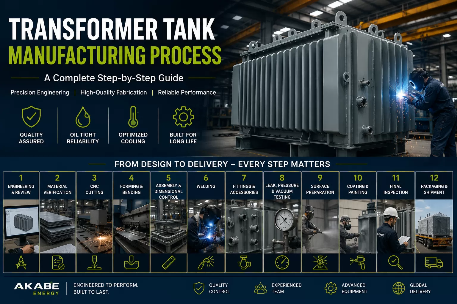
Transformer tank testing verifies that a fabricated steel enclosure is suitable for its intended service and the transformer manufacturer’s assembly and oil-processing operations. A tank must contain insulating liquid, support the active part and accessories, resist specified mechanical loads, and retain dimensional accuracy. Inspection is therefore not a single end-of-line event: it begins with design requirements and continues through material verification, fabrication, testing, coating and release.
Pressure, vacuum and leak tests answer related but different questions. A positive-pressure test examines the tank under outward loading. A vacuum test examines its resistance to external pressure and potential buckling. A leak test searches for unintended fluid or gas paths through welds, joints and fittings. None of these tests should be treated as a substitute for all the others.
Oil leakage can reduce the insulating-fluid inventory, introduce contamination pathways and create environmental and maintenance problems. Excessive deformation may compromise seals, cover alignment, accessory interfaces or the active-part envelope. Defects can be difficult and costly to repair after surface coating, shipment or transformer assembly.
A controlled inspection and test plan (ITP) establishes which characteristics will be checked, when checks occur, who witnesses them and which documents demonstrate compliance. The plan should be agreed before fabrication, especially where the buyer requires inspection hold points or third-party witnessing.
A positive-pressure test evaluates the assembled tank under a specified internal pressure. It can reveal leakage at seams, flanges and fittings, and can also identify unacceptable deformation under the test load. The pressure level, medium, duration, instrumentation and acceptance criteria must come from the approved project specification and test procedure—not from a universal number copied between transformer designs.
First, confirm that the tank configuration and temporary closures match the test procedure. Inspect connections, verify that instruments are calibrated, establish an exclusion area and apply pressure in controlled increments. Once the specified test condition is reached, monitor pressure and the structure for the required duration. Inspect the defined leakage locations using the approved method, then depressurize safely and document the outcome.
Where compressed gas is used, stored energy creates a significant hazard. Testing requires appropriate pressure limits, suitable restraints, overpressure protection and trained personnel. The specific safety controls must be determined by the facility’s approved procedure.
The acceptance decision is based on the project criteria: typically no unacceptable leakage, no unacceptable permanent deformation and satisfactory test records. A pressure change alone may not prove leakage because temperature, gas behavior and instrument uncertainty can affect readings.
Vacuum conditions can occur during transformer oil filling, degassing or other manufacturing operations. Reducing the pressure inside the tank exposes its walls and cover to a net external pressure. Large flat plates, unstiffened spans and local openings may be vulnerable to buckling even when the same tank withstands positive pressure.
A vacuum test is appropriate only when the tank is designed and specified for the required vacuum condition. Before testing, verify that the tank is correctly configured, that the vacuum equipment and gauges are suitable and that personnel can monitor critical surfaces safely. Apply the specified vacuum according to the approved procedure, hold it as required, then restore pressure in a controlled manner.
Inspection should focus on wall deflection, stiffener behavior, cover and flange distortion, and any residual deformation after pressure recovery. A successful test demonstrates compliance with the specified test condition; it does not automatically establish suitability for a more severe vacuum or a different operating configuration.
Leak testing targets unintended passages through pressure-boundary welds, corrugated-panel joints, valve connections, flanges, covers and other interfaces. Method selection depends on the specified sensitivity, geometry, accessible surfaces, test medium and stage of manufacturing.
A controlled internal gas pressure is applied and an approved leak-detection solution is used on accessible joints. Bubble formation can indicate escaping gas. The method is practical for localizing many surface leaks but may miss defects outside the method’s sensitivity or areas that cannot be observed.
A tracer gas and suitable detection instrument may be used when higher sensitivity or specific acceptance requirements apply. Equipment setup, background concentration, calibration, test boundaries and reporting units must be defined in the procedure. A tracer-gas test should not be represented as proof of a particular leak-rate limit unless that limit was actually measured and documented.
Some projects may specify liquid filling or other liquid-based checks. These introduce handling, cleanliness and drying considerations, so their suitability should be established with the transformer manufacturer. The selected method should support—not jeopardize—the subsequent assembly and oil-filling process.
Pressure test: verifies behavior under positive internal pressure; can also support leakage inspection. Vacuum test: verifies structural response to the specified external-pressure load. Leak test: evaluates oil-tightness using a defined detection method and sensitivity. The three methods are complementary; the approved ITP determines which are required for a given tank.
Visual inspection is a fundamental control for weld profile, surface discontinuities, workmanship and accessibility. Additional non-destructive examination may include liquid penetrant, magnetic particle, ultrasonic or radiographic methods, depending on material, joint geometry and the specified defect types. No single NDT method identifies every possible imperfection.
Weld inspection should be linked to approved welding procedures, welder qualifications where required, weld maps and repair records. Acceptance levels and examination extent must follow the applicable project documents and selected standards rather than an assumed blanket requirement for every weld.
A leak-tight tank may still be unsuitable if its interfaces are out of tolerance. Dimensional inspection verifies overall length, width and height; cover and flange alignment; bushing and radiator interfaces; base and mounting points; lifting and jacking arrangements; and the location of valves and other fittings.
Corrugated tanks also require checks of panel geometry and consistency. Measurements should reference the approved drawings and documented tolerances. Special attention is warranted after welding, since heat input and welding sequence can introduce distortion.
Testing and critical weld inspections are generally planned before coating conceals access to the steel surface. After surface preparation, inspectors may verify cleanliness and profile against the coating specification. Following paint application, inspection can include appearance, coverage, dry-film thickness and other specified tests.
The required coating system depends on the environment and customer specification. Coating checks do not replace structural or leak testing; they verify a separate protective function needed for long-term outdoor service.
Transformer tank projects may reference the IEC 60076 series for transformer-related requirements, along with applicable material, welding, NDT and coating standards. However, a standard’s relevance does not mean that every test, pressure level or duration is universally prescribed for every tank. Contract documents, drawings, customer specifications and approved procedures must establish the actual test scope.
Before testing, the engineering and quality teams should agree on the test configuration, medium, target condition, duration, measuring equipment, permissible deformation, leak acceptance criterion, witness requirements, safety controls and documentation format. Where requirements conflict, the discrepancy should be resolved through the project’s formal technical review process.
Weld leakage: may result from porosity, incomplete fusion, cracking or other weld discontinuities. Flange leakage: may result from misalignment, surface damage or inappropriate sealing conditions. Vacuum deformation: may point to inadequate stiffening, excessive unsupported spans or an incorrect test configuration. Dimensional nonconformance: can arise from cutting errors, fit-up variation or welding distortion. Coating defects: may be linked to poor surface preparation, contamination or application conditions.
A failed test should trigger a documented nonconformance process. The defect is located, assessed, repaired using an approved method and re-inspected or re-tested as required. Repeated defects warrant root-cause analysis rather than only local repair.
A robust release package may include approved drawings and revisions, material certificates, welding procedure records, personnel qualifications where required, weld maps, NDT reports, pressure/vacuum/leak test records, calibration information, dimensional inspection reports, coating reports, nonconformance closures and final release approval.
Traceability matters because it connects the delivered tank to the materials, processes and inspections actually used. The extent of documentation should match the purchase order and agreed quality plan.
Testing cannot guarantee a particular service life, but it reduces the likelihood that preventable fabrication defects reach the field. It also gives transformer OEMs and procurement teams objective evidence that a tank has met defined acceptance requirements before shipment. Reliable outcomes depend on sound engineering, controlled manufacturing, appropriate test methods and clear documentation working together.
When evaluating a transformer tank manufacturer such as Akabe Energy, buyers should request evidence relevant to the actual project: a sample inspection and test plan, applicable test procedures, reporting formats, weld quality documentation, calibration practices and examples of traceability records. The supplier should confirm which testing operations it performs, which are subcontracted and which are available for customer witnessing. Project-specific capabilities and certifications should be verified directly rather than assumed.
For a quotation or technical discussion, provide the tank drawings, transformer rating, oil volume, required positive-pressure and vacuum conditions, leak acceptance criteria, coating requirements and applicable customer standards. Clear inputs allow the manufacturer to assess both fabrication and verification requirements.
It is the planned inspection and verification of a transformer tank’s structural integrity, oil tightness, dimensions, weld quality and specified surface protection before acceptance.
Pressure testing checks performance under a defined positive internal pressure and may reveal leakage or unacceptable deformation.
It checks whether the tank can withstand the specified net external pressure, such as a condition associated with vacuum oil processing, without unacceptable deformation.
No. A pressure test evaluates the response to an internal load; leak testing specifically seeks unintended leakage paths using an approved detection method.
The appropriate method depends on the required sensitivity, tank configuration, available access, test medium and project acceptance criteria.
No. Test values and durations must be taken from the approved design and project requirements.
At minimum, the records required by the purchase order and quality plan, potentially including test reports, inspection records, material traceability and weld documentation.
Transformer tank testing is a coordinated verification process—not merely a final pressure check. Positive-pressure testing, vacuum testing, leak detection, weld examination, dimensional inspection and coating verification address different risks. When these activities are tied to approved design inputs, safe procedures and traceable records, transformer manufacturers and project owners can make more informed acceptance decisions.
Discuss your transformer tank requirements with Akabe Energy. Share your approved drawings, technical specifications and inspection expectations to request a project-specific manufacturing and quality review.